The interface allows you to connect an external ROM on ZX-Spectrum machine and run four different ROMs of the computer instead of the originally built-in one.
The interface uses a 64K x 8-bit memory organization system, e.g. EEPROM W27C(E) 512 – 4 banks 16KB each, switched with DIP switch, which gives us the opportunity to run 4 different ROMs.
It used for service diagnostics of ZX-Spectrum computers: memory, ULA, keyboard, EAR/MIC, image and sound. It also allows you to run modern, alternative ZX BASIC ROMs, improved over the original version from 1982.
(You may uploading your ROMs in memory, supports EPROM chips: 27C512 (64 kB – 4 banks), 27C256 (32 kB – 2 banks), 27C128 (16 kB – 1 bank). To do this, you need to have a memory chip and a programmer, the original ROM we flashed can be removed, it is installed in a reusable panel)

The interface will work properly with computers
- ZX Spectrum 48/+/128
- ZX Spectrum +2
- Timex 2048
- Harlequin 48/128
- Sizif-512
The interface does not work with ZX Spectrum 128 + 2A / B and +3 computers
J1 jumper option
When a jumper is on pins 1-2, it will enable the integrated diagnostics software.
When a jumper is off pins 1-2, it will have the ZX Spectrum boot as normal.
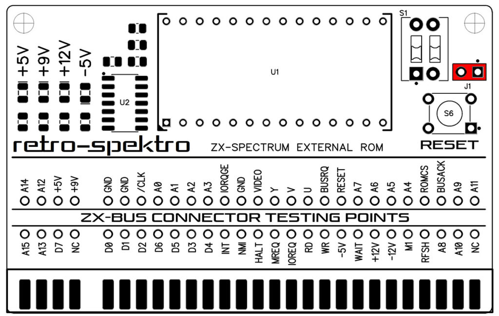
The updated revision 2.0 has a switch instead of a jumper

Testing
- Mount the interface to the ZX Spectrum edge connector with the power switched off
- Use the ROM SELECT switch S1 to select one of the four ROM banks you wish to use
- Power on computer
Including EPROM with the interface, on which the following programs are installed:
- Brendan Alford’s diagnostics ROM
- Retroleum DiagROM – diagnostic software
- Ian Logan ZX Spectrum Test ROM – diagnostic software
The interface comes with the ZX Spectrum Diagnostics software, developed by Dylan Smith and Brendan Alford.
There are more features that you can launch with holding a key directly after powering up – this is shown on screen. Hold the key until the specific feature is started
Find much more detailed info about the Integrated Diagnostic Tools on its developer’s page.
https://github.com/brendanalford/zx-diagnostics/wiki/Firmware
Retroleum DiagROM diagnostic software – download pdf manual
Power signal indicator LEDs
The green LEDs show if the voltages are present.
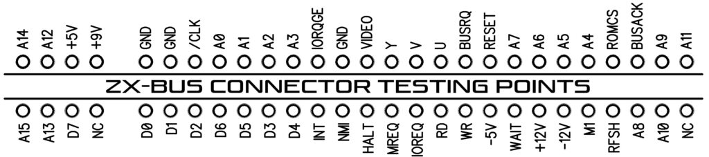
Testing points
For ease of testing, we have output all connector signals, so you can check the supply voltages of all data buses, etc.
Lower RAM tests
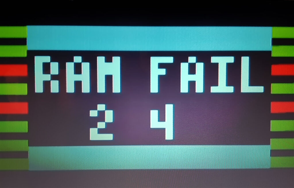
When the interface boots up, the integrated Diagnostic Tools will start with testing ‘lower RAM’.
When it finds a fault, it will most often indicate which data lines do not ‘work’ (where it is not getting data from or storing data to correctly).
The numbers correspond to these chips on the ZX Spectrum:
Sometimes it’s not a chip that is defective, but the feeding voltages are unstable.
Always replace all original electrolytic capacitors first when this kind of fault is detected.
Another cause of lower memory errors can be a failing address line or something else like a problem with the control signals to the memory chips.
Also the ULA chip could be faulty.
The best way to check is not by putting in another ULA in the board with the problem. Instead of put the potentially defective ULA chip in a working board to test it.
Upper RAM tests
When an error is detected, it will often show which chip is actually faulty.
Is when working on an original 16/48K machine, or a 128K+ toastrack.
When using the intarface on a Harlequin boards, these chip numbers obviously do not make any sense (it does that since it detects the machine by the used ROM, so the interface may think your Harlequin board is actually a real ZX Spectrum).

Example showing memory failure on two computers