
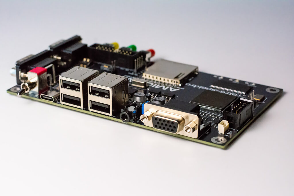
The Amicom board based on Till Harbaum existing Mist FPGA design, and is fully compatible with the original version’s cores.
Since the original PCB is unavailable, we routed our own version to implement classic 16 bit computers like the Amiga, Atari ST(E) or the Apple Macintosh (and even early 32 bit computers like the Acorn Archimedes) as a System-on-a-Chip using modern hardware.
But it equally well supports 8 bit systems like the Atari 800/XL, ZX81, ZX Spectrum, C64, Atari VCS, Atari 5200, Colecovision, Apple II, Sega Master System, Nintendo Gameboy, Nintendo NES, Odyssey2 plus others and 16 bit consoles SNES, Genesis/Megadrive, PC Engine.
It also supports over 500 Arcade games.
Hardware board built around a field programmable gate array (FPGA). FPGAs are chips that can be configured to implement complex user specific logic functions.
The board boots from the internal flash memory of the IO controller and from SD card. You just place a matching file named core.rbf containing the FPGA configuration on the SD card (NTSC or exFAT compatible) and have that inserted when powering the board on. In case of e.g. a simple arcade machine core this may already be all you have to do and games like pacman are immediately working. More complex cores like the Minimig/Amiga core may require additional files which will be used by the core when booting.


Video
Typically all devices emulated by the Amicom used TV screens in PAL or NTSC timing. These video timings are incompatible with todays VGA screens.
The original Amiga used a PAL or NTSC TV video mode and wasn’t able to directly drive a VGA screen. The Minimig uses a scan doubler to create a video timing from the PAL/NTSC mode that’s close to a valid VGA video mode, but in the case of PAL has a vertical refresh rate of 50Hz which is below the minimum required vertical VGA refresh rate of 56Hz. Many displays cope with this signal. But many displays don’t. The symptoms range from no image at all to an error message (“frequency out of range”) to images being partial off-screen or having wrong colors or being otherwise distorted.
One option to deal with this is to select an NTSC video mode on the OSD (see below). The resulting VGA mode is compatible to the 640×480 VGA mode and works fine with all VGA displays. But many games require a PAL video mode to run properly.
The board optionally comes with Minimig cores that are slightly “overclocked”. The CPU inside runs at 8MHz instead of the 7MHz of a real Amiga and everything is 10% faster. Games will run slightly faster and may be more difficult to master and sounds and music will have a slightly higher pitch. But the advantage is that the PAL video mode then uses a vertical refresh rate of 56Hz and displays fine on all VGA displays tested so far.
The core converts the Atari ST video modes into standard VGA compatible video modes. These video modes are not 100% compatible with the original ATari ST modes and some Atari ST software (especially games and demos) may not be displayed properly.
Input devices
Keyboards and mice
Unlike other Minimig based systems the board uses USB instead of PS/2 to connect keyboards and mice. The main advantage is that you can use the majority of recent keyboards and mice and even combo devices, touch pads and similar are likely to work.
The board comes with a built-in USB hub and features four USB host ports (the fifth USB port next to the push buttons is a device port and is used to connect a PC during firmware update). You can connect further USB hubs to these ports. Also keyboards with built-in hubs are supported.
Although you can connect several mice and keyboards at the same time they are treated as one device. Later versions may support several distinct mice to support multi mouse games.
Using the On-Screen-Display
The Minimig core is controlled using an on screen display (OSD). The OSD can be invoked with the F12 key. Use the OSD to insert disk images into the emulated floppy drives or to change the total amount of memory visible to the embedded Amiga. Also the hard drive emulation can be enabled here.
Using mouse and joystick emulation
The NumLock key toggles a mouse or joystick emulation. The mouse and joystick emulation uses the arrows keys on the keyboard and the two ctrl keys to emulate mouse and joystick input. Pressing the NumLock key cycles through four states indicated by the NumLock and ScrollLock LEDs on the keyboard:
Both LEDs off: Normal mode, no emulation
Both LEDs on: Mouse emulation
Only NumLock LED on: Emulation of joystick 1
Only ScrollLock LED on: Emulation of joystick 2
Joysticks
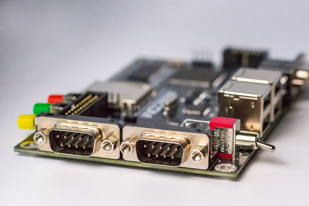
The board supports up to two standard DB9 Atari/Commodore style joysticks. The joysticks are provided with 5 Volts (up to 200mA total) in order to allow for auto fire and similar devices to work. No mice are supported on these ports. A built-in switch logic of the Minimig switches forth and back between the USB mouse and a joystick in the right joystick port to allow the convenient usage of two joysticks and a mouse without having to unplug anything.
Main Components
Altera Cyclone EP3C25 FPGA (24,624 Logic Elements. 66 M9K blocks)
32 Megabytes 16 bit wide SDR SDRAM
AT91SAM7S56 ARM IO controller
MAX3421E USB host controller
TUSB2046 USB HUB
External Connectors, buttons and LEDs
4 USB host ports
18 bit analogue VGA output for 256.000 simultaneous colors
Stereo analog audio output
Tape input and output
Type-C USB for Power Supply and IO Controller flash update
2 classic DB9 Atari style joystick connectors
SD Card slot
3 LEDs (Power, FPGA and IO Controller)
3 Pushbuttons (Board Reset, Menu, Core defined)
Power Switch
Internal Connectors, switches and jumpers
1 Flash Jumper for IO Controller flash update via Type-C
2 DIP switches (FPGA bypass, core defined)
ARM JTAG connector for ARM IO Controller development and debugging
FPGA JTAG connector for FPGA development and debugging
ARM Debug connector for development
FPGA Expansion connector for MIDI/RS232/Debugging/